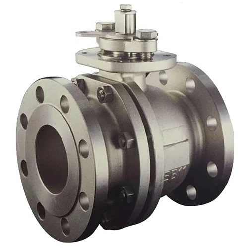
Lift Check Valve
- Size Range
- NPS1/ 2′′~NPS 16′′ DN15-DN400
- Temperature Range
- -20~350°C
- Pressure Rating
- CLB150~CL300 PN10~PN40
Specification Parameters
| Name | Lifting check valve |
| Size | NPS1/ 2′′~NPS 16′′ DN15-DN400 |
| Pressure | CLB150~CL300 PN10~PN40 |
| Temperature | -20~350°C |
| Application range | Water, sewage, construction, food, medicine, textile, electricity, shipbuilding, metallurgy, energy systems |
| Body Material | Stainless steel 304, 316, cast steel |
Design Specification
| Design and Manufacturing | ANSI B 16.34 or BS 1873 |
| Structure length | ANSI B 16.10 |
| Flange Standard | ANSI B 16.5a |
| Terminal end size | ANSI B 16.25 |
| Pressure test | API 6D or API 598 |
| pressure and temperature rating | ASME B16.34, GB/T 12224 |
Product Description
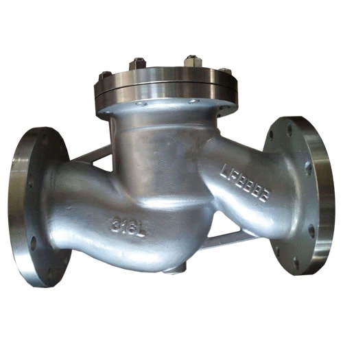
The lift check valve refers to a valve that automatically opens and closes the valve flap by means of the flow of the medium itself, and is used to prevent the back flow of the medium, also known as a check valve, a check valve, a reverse flow valve, and a back pressure valve. The check valve is an automatic valve whose main function is to prevent backflow of the medium, prevent the pump and drive motor from reversing, and discharge the container medium. The check valve can also be used to supply a line in which the pressure may rise to an auxiliary system that exceeds the system pressure. The check valve can be mainly divided into a swing type check valve (rotation according to the center of gravity) and a lift check valve (moving along the axis).
The valve flap of the lift check valve is located on the seat sealing surface of the valve body. In addition to the valve flap being free to lift and lower, the valve is like a shut-off valve. The fluid pressure causes the valve flap to lift from the valve seat sealing surface. The return of the medium causes the valve flap to fall back to the valve seat and shut off the flow. Depending on the conditions of use, the flap may be of an all-metal construction or may be in the form of a rubber or rubber ring on the valve disc holder.
Get in Touch
Contact Us
Dongou Industrial Zone,Oubei Town,YongJia, WenZhou City,ZheJiang Province P.R China
